


Aluminum Stair Railing Inspection: Height, Openings, and Anchorage
Aluminum Stair Railing Inspection: Height, Openings, and Anchorage
An aluminum stair railing can look flawless yet fall short on critical safety checks. For quality control teams and safety managers, inspection should focus on three essentials: height, openings, and anchorage. Are measurements taken from the correct reference points? Could gaps create a fall or entrapment hazard? Are posts and fasteners securely connected to a suitable supporting structure? A useful inspection answers these questions with measurements and evidence—not simply a visual acceptance of the finish.
The challenge is that a railing is both a manufactured assembly and a site-installed safety system. Factory dimensions may be correct while finished flooring changes the installed height. Approved anchors may still be unsuitable for the actual slab edge. Inspection therefore needs to connect the shop drawings, delivered components, and completed installation before handover.
Establish the acceptance criteria before taking measurements
Start by distinguishing a handrail from a guard. A handrail provides a graspable support along the stair. A guard protects an open edge against falls. One assembly may serve both purposes, but meeting the height requirement for one function does not automatically satisfy the other. A wide decorative top rail, for example, may form part of a guard without qualifying as a graspable handrail.
Identify the governing jurisdiction, adopted code edition, occupancy classification, approved drawings, and project specifications. Residential and commercial requirements can differ, and local amendments matter. Where documents conflict, obtain clarification from the responsible designer or authority having jurisdiction rather than choosing the easiest requirement to meet.
For orientation, U.S. International Residential Code provisions commonly specify handrail heights of 34–38 inches, measured vertically from the sloped plane adjoining tread nosings. Residential guards commonly require at least 36 inches on level walking surfaces, with different provisions along stair flights. The International Building Code commonly uses a 42-inch guard requirement, subject to stated exceptions. These are reference examples, not a universal acceptance schedule; confirm the adopted provisions for the particular installation.
Prepare an inspection sheet showing each applicable limit, its measurement reference, and the document establishing it. Include approved post spacing, anchor details, substrate requirements, and any required structural testing. Missing acceptance criteria should be resolved before installation approval—not left for an inspector to interpret at the stair.
Height: measure from the finished stair geometry
On a stair flight, measure vertically, not perpendicular to the inclined rail. Establish the reference line through the tread nosings and measure to the top of the applicable handrail or guard. On a landing, use the finished walking surface. Confusing these reference points can produce an apparently acceptable reading that does not represent the code-defined height.
Check the lower end, upper end, intermediate locations, and every transition. A railing can follow the correct slope overall but dip at a joint or change height where a flight meets a landing. Uneven tread finishes can also change the relationship between the nosing line and the rail.
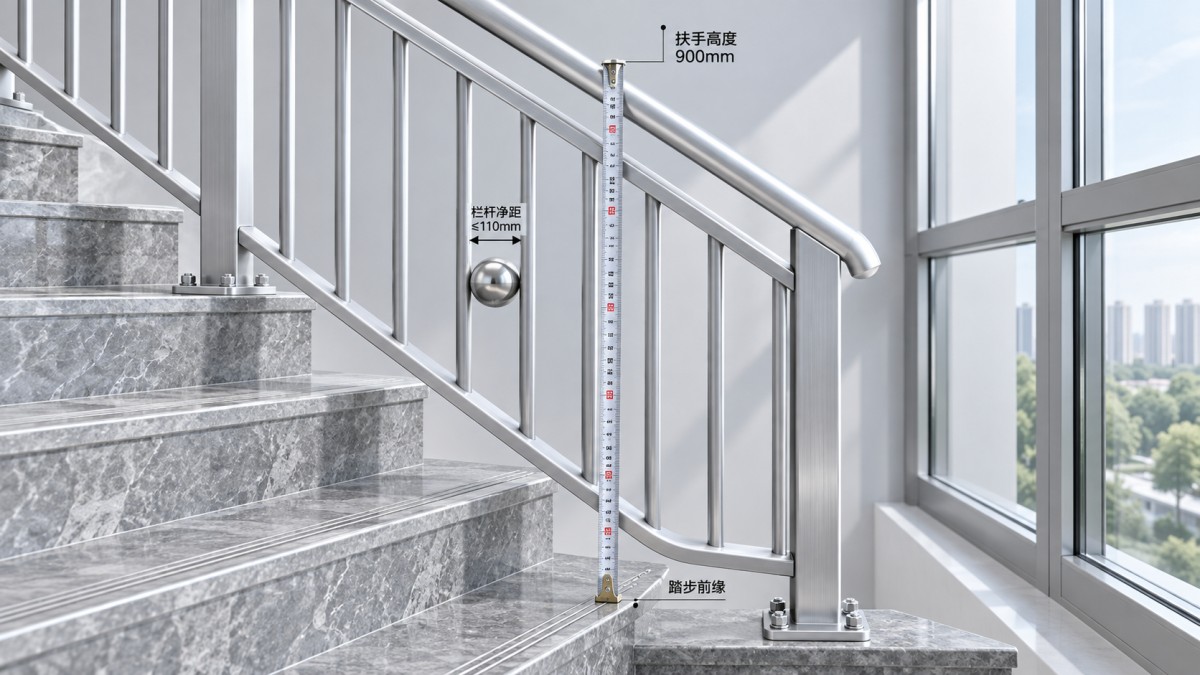
Floor buildup deserves particular attention when railing installation precedes tile, stone, or other finishes. Record unfinished-surface measurements as provisional, with the expected finish thickness identified. Final acceptance should use the completed walking surface. Do not assume a dimension checked against bare concrete remains valid after flooring is added.
Height inspection should also capture handrail usability. Check continuity, graspability, clearance from adjacent walls, and required extensions or returns under the applicable rules. Near doors and windows, verify that trim, handles, and opening leaves do not obstruct the intended grip or create a collision point. These interface defects are easily missed when each trade inspects only its own work.
Openings: inspect the largest clear gap, not the nominal spacing
A drawing dimension between baluster centerlines is not the same as the clear opening. Inspect the actual space between installed components, including gaps beside posts, beneath bottom rails, and around decorative infill. The widest opening may occur at a termination rather than in the repeating middle section.
Many U.S. model-code guard provisions use a 4-inch sphere criterion for general openings. Certain stair provisions permit a 4⅜-inch sphere, while the triangular opening formed by the tread, riser, and bottom rail may use a 6-inch sphere criterion. These exceptions apply only where the governing code allows them. A triangular-opening allowance should not be applied to every gap along a stair.
Use an appropriate rigid gauge or sphere where the acceptance rule is defined that way. A tape measure can help locate suspect gaps, but a single measurement may not establish whether a sphere passes through an irregular opening. Do not force the gauge or spread the infill; assess deformation separately under the specified structural procedure.
Pay close attention to these less obvious locations:
- Sloped bottom rails, where the clearance changes across each tread.
- Post-to-wall terminations, especially where wall finishes are incomplete.
- Decorative cast panels, whose curved shapes can conceal larger openings.
- Field-cut infill sections, where accumulated tolerances alter the final gap.
Passing an opening-size check does not establish suitability for every setting. Child-accessible areas, pools, and other special occupancies may have additional restrictions, including configuration or climbability requirements. Assess those against the relevant provisions rather than treating ordinary stair-guard dimensions as sufficient.
Anchorage: follow the load path into the supporting structure
Anchorage is often the least visible part of an aluminum stair railing and the most difficult to verify after completion. The load path runs through the rail, infill connections, posts, base plates or side brackets, fasteners, and supporting structure. A sound-looking post does not prove that every connection in that path is adequate.
Compare the installed assembly with the approved structural details. Confirm post spacing, connection geometry, anchor type and quantity, embedment, edge distances, and substrate condition. A detail designed for reinforced concrete cannot simply be transferred to masonry, thin steel, or timber without review. Likewise, changing from top-mounted to side-mounted posts changes the connection conditions.
Verify what the anchors actually engage
Tile, screed, cladding, and waterproofing layers are not substitutes for the specified structural support. Check that embedment is measured into the intended substrate, not from the top of a finish layer. For timber construction, confirm the designed blocking or framing connection rather than assuming decking alone provides adequate resistance.
Concrete edges require particular care. Look for cracking, spalling, misplaced holes, and insufficient distance to an edge. For adhesive anchors, installation records should address the specified drilling and hole-cleaning method, adhesive identification, embedment, and curing conditions. For mechanical anchors, verify the manufacturer's installation requirements, including torque where specified. Tightening an anchor harder is not an acceptable remedy for an unsuitable hole.
Inspect connections without improvising a proof test
Loose fasteners, moving base plates, cracked welds, and visible joint separation require investigation. A controlled manual check may reveal looseness, but it cannot demonstrate compliance with design loads. Where proof testing is required, use an approved procedure defining the load, application point, equipment, acceptance criteria, and safety precautions. Uncontrolled pushing or pulling can damage the assembly without producing meaningful evidence.
Inspect moisture and material interfaces as well. Aluminum connected to dissimilar metals may need specified isolation in wet or corrosive environments. Base details should preserve drainage and waterproofing. Decorative covers can hide loose fixings or trapped water, so complete concealed-work checks before covers are fitted and retain photographs of the connections.
Separate product appearance from evidence of suitability
A coordinated door, window, and railing package can simplify finish selection, but shared appearance does not establish shared performance. Aluminum Art manufactures doors, courtyard gates, guardrails, stair handrails, and accessories from a building-materials trading location with transport and logistics access. For inspection purposes, the useful connection is component coordination: drawings, supplied brackets, accessories, and installation instructions should describe the same approved assembly.
For example, the aluminum GFR-54 Aluminum alloy fence is presented for residential and commercial projects, with durability and clean aesthetics among its stated advantages. Those attributes may inform a coordinated design, but they do not establish approval as a stair guard. Confirm the intended application, dimensions, connection details, and relevant performance evidence before substitution. Thermal-efficiency language associated with doors and windows is not evidence of railing safety or anchorage capacity.
A manufacturer's emphasis on quality and easier installation is most useful when supported by clear component identification and repeatable assembly details. Factory inspection should check supplied dimensions and connections; site inspection should verify the resulting installation. Neither replaces the other.
Close defects with evidence, not a general sign-off
Record each defect by stair and location, including the measured condition, acceptance requirement, photograph, and corrective action. “Railing too low” is less useful than a reading tied to a specific nosing reference. “Anchor issue” should identify whether the concern is missing hardware, uncertain embedment, substrate damage, or an unauthorized substitution.
Reinspect after correction. Moving a post can alter adjacent openings; replacing a bracket can affect clearance or waterproofing. Where a safety-critical condition remains unresolved, restrict access through the project's safety procedures rather than treating a punch-list entry as adequate protection.
Handover should leave a traceable record of the accepted geometry, concealed anchorage, approved deviations, and maintenance requirements. If a critical connection cannot be verified, arrange further investigation before approval. A clean finish is easy to see; a defensible acceptance decision requires knowing what supports it.
Related Posts
CONTACT US

First class quality service and professional after-sales team.
Get in Touch
*We respect your confidentiality and all information are protected.