


Choosing an Aluminum Gate Motor by Gate Weight, Wind Load, and Duty Cycle
An aluminum gate motor should be selected against three conditions together: the complete gate’s weight and dimensions, the force needed to move it under the site’s permitted wind conditions, and the busiest operating period it must handle. A model that passes only the weight check can still stall on a broad, solid leaf or overheat during repeated entry and exit movements.
For technical evaluation, begin with the manufacturer’s approved gate size and weight limits, then verify the installation geometry, wind assumptions, and duty rating behind those limits. The best choice is an operator with documented capacity for the actual installation and a workable safety setup. Extra motor power alone cannot compensate for poor hinges, flexible mounting points, or an unsuitable operating arrangement.
Start with the complete gate and its movement
Establish whether the entrance uses swing leaves, a tracked sliding gate, or a cantilever sliding gate before comparing operators. These arrangements create different loads. A swing operator works through a changing lever arm around the hinge axis. A sliding operator produces linear drive force through a rack or another transmission, while wheels, guides, track condition, and alignment determine much of the resistance.
Use the weight of the finished moving assembly. Include infill, decorative castings, reinforcement, attached hardware, and accessories that move with it. Aluminum construction can reduce weight, but a material description does not establish the load. A heavily decorated aluminum leaf may demand a different operator from an open aluminum frame of the same dimensions.
For a swing gate, leaf width deserves as much attention as weight. A wider leaf has greater rotational inertia and gives wind a longer lever arm. Its acceleration demands and wind-induced hinge moment can therefore exceed those of a narrower leaf with the same mass. Read weight and width limits as a permitted combination; do not assume the maximum published weight and maximum published width can be used simultaneously.
Before sizing the drive, move the gate manually through its full travel with the operator disengaged, following the equipment’s release procedure. Look for binding, sagging, inconsistent resistance, and movement caused by slope or misalignment. On a sliding gate, inspect the entire travel path. On a swing gate, check hinge alignment and whether the leaf remains stable at different opening angles.
Mechanical faults should be corrected before motor selection. Increasing the force setting to overcome a tight hinge or damaged track makes the load unpredictable and can interfere with obstacle detection. It also leaves the evaluator unable to distinguish normal operating resistance from a developing fault.
Translate wind exposure into a load the operator can handle
A broad aluminum gate with solid infill can be light enough to pass a weight chart and still impose substantial wind loads. The exposed area, infill permeability, leaf width, opening angle, and surrounding buildings all affect the result. A sheltered entrance and an entrance facing an open approach should not automatically receive the same operator specification.
For an initial engineering assessment, wind force can be expressed as effective pressure multiplied by exposed area. For a swing leaf, that force creates a moment around the hinges:
Wind moment ≈ effective wind pressure × exposed area × distance from the hinge axis to the center of pressure.
The effective pressure must account for the relevant wind condition and aerodynamic assumptions. For a simple rectangular solid leaf under an assumed uniform pressure, the center of pressure can be approximated at half the leaf width. Perforated infill, irregular shapes, nearby walls, and different gate angles can require a more detailed assessment. An opening percentage alone does not provide a reliable reduction factor for every mesh or slat arrangement.
As an illustrative calculation, consider a solid leaf 2 meters wide and 1.8 meters high under an assumed effective pressure of 300 pascals. Its area is 3.6 square meters, giving a force of 1,080 newtons. With the force acting 1 meter from the hinge axis, the resulting hinge moment is approximately 1,080 newton-meters. This example shows how leaf area and width affect demand; the assumed pressure is not a site design value.
That hinge moment cannot be compared directly with the thrust rating of a linear actuator. Actuator force produces turning moment through the perpendicular distance between its line of action and the hinge axis. That distance changes as the gate opens. A mounting arrangement with a small effective lever arm may require considerable actuator force, particularly at certain points in the travel.
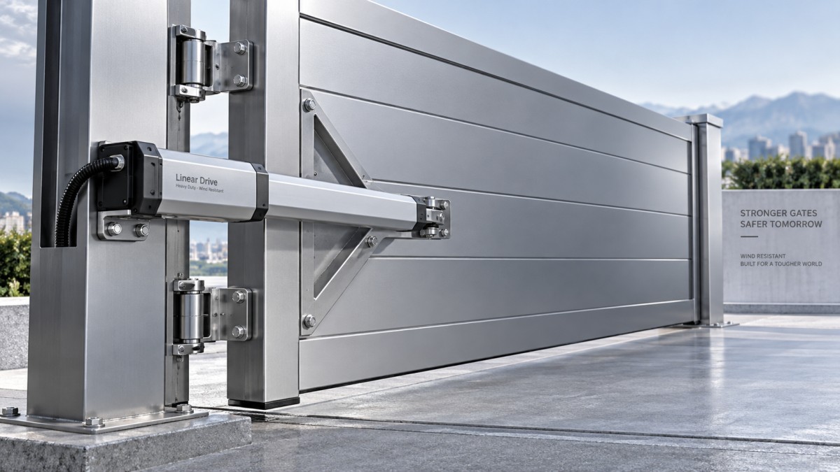
Check the proposed bracket positions against the operator’s installation drawings, including hinge offset, post dimensions, opening angle, and available stroke. A drive that appears suitable on a weight chart may become unsuitable when installed on a deep post or with restricted mounting space. Articulated-arm and underground operators have their own geometry requirements and should be assessed using their specific documentation.
Wind can oppose movement, assist it, or reverse its effect during a cycle. The evaluation therefore needs to cover controlled motion and stopping as well as the ability to start. A motor that can push a leaf open may still struggle to control a wind-assisted closing movement. Holding the gate stationary introduces another requirement, potentially involving a lock, brake, or mechanical restraint.
Separate the wind condition in which the gate must operate from the wind condition the closed gate and its supports must withstand. If operation is restricted above a defined wind threshold, establish how that restriction will work and how access will be managed. The operator should not be treated as the structural restraint for severe weather unless its manufacturer explicitly supports that use and the gate system has been designed accordingly.
Size duty cycle around the busiest period
Daily traffic totals are insufficient for selecting duty capacity. An entrance with arrivals spread across the day presents a different thermal demand from one handling a concentrated morning queue. Hotels, shared residential entrances, and service access points can experience bursts that disappear inside an apparently modest daily average.
Record the expected movements during the busiest hour and during the longest likely uninterrupted burst. Establish whether the supplier counts a “cycle” as one opening movement or a complete opening-and-closing sequence. Also identify the travel time at the intended speed, since wider swing angles and longer sliding travel keep the motor running for longer.
A useful first calculation is:
Motor running fraction = total motor running time during the assessment period ÷ length of that period.
For example, if a hypothetical complete cycle requires 40 seconds of motor operation and occurs 30 times in an hour, the motor runs for 1,200 seconds, or one-third of that hour. A gate-open pause generally does not add motor running time when the drive is stationary. However, the spacing between movements still affects cooling, so the same hourly running fraction can produce different thermal conditions.
Compare the resulting demand with the manufacturer’s rating under its stated conditions. A percentage duty rating, cycles-per-hour limit, and continuous-duty designation are not automatically interchangeable. Ask what ambient temperature, gate load, travel time, and rest periods apply. Direct sun, an enclosed installation, and high local temperatures may change the available thermal margin.
Repeated starts, reversals, and interrupted movements also matter. A busy entrance may require more motor activity than the access-control count suggests if vehicles trigger reopening or pedestrians interrupt closing. Evaluate a credible busy-period sequence, rather than assuming every vehicle produces one clean cycle with an identical rest interval.
A supply-voltage description does not establish duty capacity. Assess the complete operator’s motor, gearing, control system, and thermal protection. If backup power is required, check its supported operation under the specified gate load; a battery provision alone does not establish how many movements remain available.
Read capacity ratings as installation limits
Shortlisting becomes more reliable when each supplier receives the same gate schedule: movement type, finished weight, dimensions, infill arrangement, mounting geometry, required speed, environmental conditions, and peak operating sequence. Without those inputs, apparently comparable recommendations may be based on different assumptions.
A maximum gate weight is useful for screening, but it leaves several questions unresolved. Published capacity may depend on a particular leaf length, mounting configuration, or favorable mechanical condition. The operator’s nominal thrust may also differ from its brief maximum thrust. Ask which rating represents usable operating capacity and how it applies across the proposed travel.
For the final comparison, seek written confirmation of:
- The approved combination of gate weight, leaf width or travel length, and installation geometry.
- The wind assumptions used for operation, stopping, and holding, including any operating restrictions.
- The supported peak cycle demand at the relevant ambient conditions and travel settings.
- The required locks, stops, mounting reinforcement, and safety devices for the installation.
Allow capacity margin for credible variation, including temperature, normal wear, and the assessed operating loads. An arbitrary oversizing percentage is a weak substitute for those checks. A larger operator may increase available force without resolving a poor lever arm, inadequate mounting reinforcement, or an unacceptable wind exposure.
Mounting strength deserves particular attention on aluminum assemblies. Concentrated forces from brackets and fixings must reach suitable reinforcement and supporting structure. A profile thickness by itself does not establish connection capacity. Confirm the attachment detail with the gate fabricator so that the motor’s force can be transferred without local deformation or loosening.
Make safety and commissioning part of the selection
Capacity is only useful if the gate can operate with appropriate protective measures. Force limitation, presence detection, protective edges, guarded hazard points, and manual release must be considered for the actual layout and applicable requirements. Vehicle detection equipment should not automatically be assumed to protect pedestrians or every trapping location.
Wind creates a difficult boundary here: it can raise the force needed for normal movement while the system must still respond safely to an obstruction. If reliable operation requires force settings that prevent an acceptable protective response, reconsider the leaf design, installation geometry, operating wind limit, or operator arrangement. Greater thrust does not remove that conflict.
Commissioning should verify full-travel movement, stopping, protective responses, manual release, and a representative burst of operation within the specified conditions. Record the installed bracket geometry, control settings, and any operating restrictions. These details give maintenance personnel a baseline and help reveal whether later problems originate in the drive, the gate mechanics, or changed site conditions.
The final selection should leave the evaluator able to explain why that operator suits that gate: its capacity covers the finished assembly and geometry, its wind capability matches the operating policy, and its thermal rating supports the busiest expected use. Where a supplier’s recommendation cannot connect those conditions to documented limits, the equipment is not yet ready for specification.
Related Posts
CONTACT US

First class quality service and professional after-sales team.
Get in Touch
*We respect your confidentiality and all information are protected.