


How an Aluminum Louver Roof Controls Sunlight and Drains Rainwater
How an Aluminum Louver Roof Controls Sunlight and Drains Rainwater
An aluminum louver roof manages two competing demands: admitting useful daylight while directing rainwater away from the space below. Performance depends on more than adjustable blades. Louver geometry, closing tolerances, gutter capacity, and drainage paths through the supporting structure all affect whether the space remains comfortable and usable.
The distinction matters beside glazed doors, above hotel terraces, and in enclosed courtyards. A roof may provide effective midday shade yet admit low-angle afternoon glare. It may also handle steady rainfall but overflow when leaves restrict an outlet. Evaluating these conditions separately gives a clearer picture than relying on a general claim of “sun and rain protection.”
Sunlight control starts with orientation, not the motor
Rotating louvers change the openings through which sunlight passes. However, blade angle alone does not describe the shading performance. The result depends on blade width, spacing, profile depth, rotation axis, and the sun’s position relative to the roof.
When viewed along the incoming solar rays, adjacent blades must overlap sufficiently to block direct sunlight. A position that shades the floor at noon may leave bright bands across a dining table later in the day. This is particularly noticeable where the roof faces an open western exposure: low-angle sun can enter beneath the perimeter even when the louvers are closed.
For a useful assessment, request a shading study using the actual site orientation and occupied hours. Show where people sit, where glass doors are located, and which surfaces are sensitive to glare. A simple plan showing north is not enough if the main concern is afternoon sunlight reaching a hotel lobby through a glazed opening.
There is also a practical trade-off. Closing the blades increases direct shade but reduces the open area available for daylight and upward airflow. An intermediate position can be more comfortable in dry weather, provided it blocks the relevant solar angle. It should not be assumed to offer the same rain protection as the fully closed position.
Roof shade and indoor thermal performance are different questions
Shading a glazed façade can reduce direct solar exposure, but an outdoor louver assembly is not automatically an insulated roof. Aluminum conducts heat readily, and comfort beneath the roof still depends on ventilation, surrounding surfaces, humidity, and wind. Where the terrace connects to conditioned indoor space, assess the doors’ glazing, thermal breaks, and air seals separately. The roof cannot compensate for a poorly specified building-envelope opening.
Closed blades must create a continuous water route
In a rain-managing design, closed louvers form a connected collection surface. Water runs into channels incorporated into or alongside the blade profiles, moves toward the intended blade ends, and enters perimeter gutters. Outlets then discharge it through downpipes, sometimes concealed inside supporting posts.
That description is common, but the actual route varies between systems. Some profiles use overlapping edges; others incorporate seals or additional collection channels. The important drawing is therefore a section through the closed blades and gutter connection—not just a rendering of the finished canopy.
Trace the water path from the middle of the roof to its final discharge point. Look for places where water must cross a joint, change direction sharply, or pass through a narrow opening. Blade-end details deserve particular attention because they connect moving components to fixed gutters. A generous gutter does little good if water escapes before reaching it.
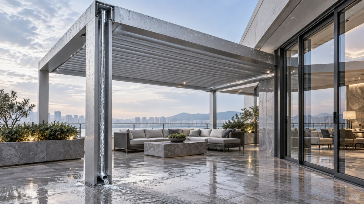
Slope must also be understood correctly. A roof that appears level from below may use shaped internal channels or a specified installation fall. Do not assume either arrangement. Ask which surfaces establish drainage fall and what installation tolerances apply. Unplanned sag or a reversed fall can retain water, increasing the chance of dripping when the blades reopen.
Closing accuracy is a weather-performance detail
A motor reaching its stopping position does not prove that every blade has seated correctly. Linkage adjustment, bearing alignment, frame squareness, and blade deflection all influence the final gaps. On a larger assembly, a small alignment problem can affect several joints rather than one isolated point.
Where seals are used, they need suitable contact without excessive compression. Too little contact can leave leakage paths; too much can increase operating resistance or accelerate wear. EPDM or silicone components may be appropriate, but the material name alone does not establish performance. Seal shape, retention, exposure conditions, and replacement access matter as well.
Wind-driven rain introduces another complication. Water does not always fall vertically, and pressure can drive it through joints that perform adequately in calm rainfall. Any weather-resistance claim should identify the tested configuration, rainfall conditions, wind conditions, and acceptance criteria. “Waterproof” without these boundaries is not a useful technical specification.
Size the drainage system for the site, not the appearance
Drainage capacity begins with the contributing roof area and the design rainfall intensity required for the project location. A basic flow estimate is:
Flow in liters per second = rainfall intensity in millimeters per hour × contributing area in square meters ÷ 3,600.
For illustration only, a 100-square-meter collection area under rainfall of 100 millimeters per hour receives approximately 2.78 liters per second, assuming all rainfall becomes runoff. This is not a recommended design intensity or a gutter sizing result. Local requirements, hydraulic calculations, and the actual roof arrangement must establish the design basis.
The calculation also needs to consider whether adjoining surfaces contribute water. A louver roof beneath an existing roof edge should not inadvertently receive runoff that its drainage system was never designed to carry.
The limiting component may be an outlet, a bend inside a post, or the connection to the site drainage—not the perimeter gutter itself. Concealed downpipes keep the appearance clean, but they can make inspection and blockage removal harder. Access should be designed in rather than left to the installer.
Ask where water goes if an outlet becomes blocked. An intentional overflow route should keep water away from electrical equipment, door thresholds, and vulnerable wall junctions. A concealed system without a defined overflow strategy can hide a problem until water appears somewhere expensive to repair.
The connection to doors and walls needs its own review
At a building façade, roof drainage and door weather resistance must work together without being treated as one system. Position the gutter discharge so it does not wash across a sliding-door track. Where a canopy meets a wall, specify the flashing or weatherproof junction appropriate to that wall construction; a surface bead of sealant should not be assumed sufficient for every detail.
A hotel terrace illustrates the coordination issue. Aluminum Art’s Aluminum Electric Sliding Door, identified as DM-1021, lists thermal-break aluminum profiles, 2.0 mm profile thickness, and EPDM or silicone sealing among its supplied details. These are relevant to the adjacent opening, not evidence of the roof’s drainage performance. Door operating configuration, threshold drainage, and project-specific ratings still require confirmation.
Aluminum Art’s manufacturing scope includes cast aluminum doors, courtyard doors, guardrails, stair handrails, and related accessories. When several metalwork packages meet on one project, coordinated drawings are valuable: post bases, railing fixings, and door clearances can compete for the same space. Convenient transport and logistics help delivery, but they do not resolve an obstructed drainage outlet or conflicting installation sequence.
Controls help, but they do not replace hydraulic design
Rain sensors can command closure, yet detection and blade travel take time. Some water may enter before the roof reaches its rain-managing position. Sensor location, response settings, and power availability therefore belong in the review, especially above furniture or pedestrian routes where sudden wetting matters.
Wind control needs a documented operating strategy. The preferred blade position during strong wind depends on the particular system’s engineering; it should not be guessed from another manufacturer’s instructions. Confirm what happens when wind and rain commands conflict, and distinguish permitted operating conditions from structural resistance limits.
Reopening deserves attention too. Residual water may remain in blade channels after rainfall stops. Immediate rotation can release that water below. Check whether the operating instructions require a delay or another procedure, and confirm how manual operation works during a power failure.
What to verify before acceptance
A useful technical submission ties claims to the actual roof dimensions, support conditions, and drainage arrangement. Test evidence from a smaller or differently configured assembly may inform the assessment, but its applicability needs explanation. Structural checks should address local wind and any applicable snow loads separately from rainwater management.
- Obtain closed-blade sections, outlet details, installation tolerances, and the final discharge layout.
- Request the drainage design basis and identify inspection, cleaning, and overflow provisions.
- Confirm applicable local requirements and the scope of any cited testing; do not assume a door or window rating covers the overhead assembly.
- Agree on commissioning checks for closure, sensor behavior, water routing, and abnormal dripping before installation begins.
A controlled site water check can reveal installation defects, although it does not replace specified laboratory testing. Inspect corners, blade ends, wall junctions, and post outlets while the system drains. Also review maintenance access: gutters near trees need cleaning, and seals and linkages need periodic inspection.
The strongest aluminum louver roof proposal makes both paths clear: the path of sunlight at occupied hours and the path of water under defined rainfall conditions. If either disappears behind a rendering or an unqualified performance claim, request the missing drawing or evidence before approving the system.
Related Posts
CONTACT US

First class quality service and professional after-sales team.
Get in Touch
*We respect your confidentiality and all information are protected.