Evaluating an aluminum sliding system requires more than checking dimensions or finish quality. Its ratings must apply to the configuration and exposure conditions your project requires.
For technical assessors, sash weight capacity, air leakage, and water resistance reveal whether a configuration can meet project demands under defined operating and exposure conditions.
This guide explains how to interpret these ratings, compare test results, and identify the effects of hardware, seals, drainage, and installation on actual performance.
By distinguishing tested performance from marketing claims, you can make more defensible specification decisions and reduce the risk of difficult operation, drafts, or water ingress.
Does the Test Report Cover the System You Are Specifying?
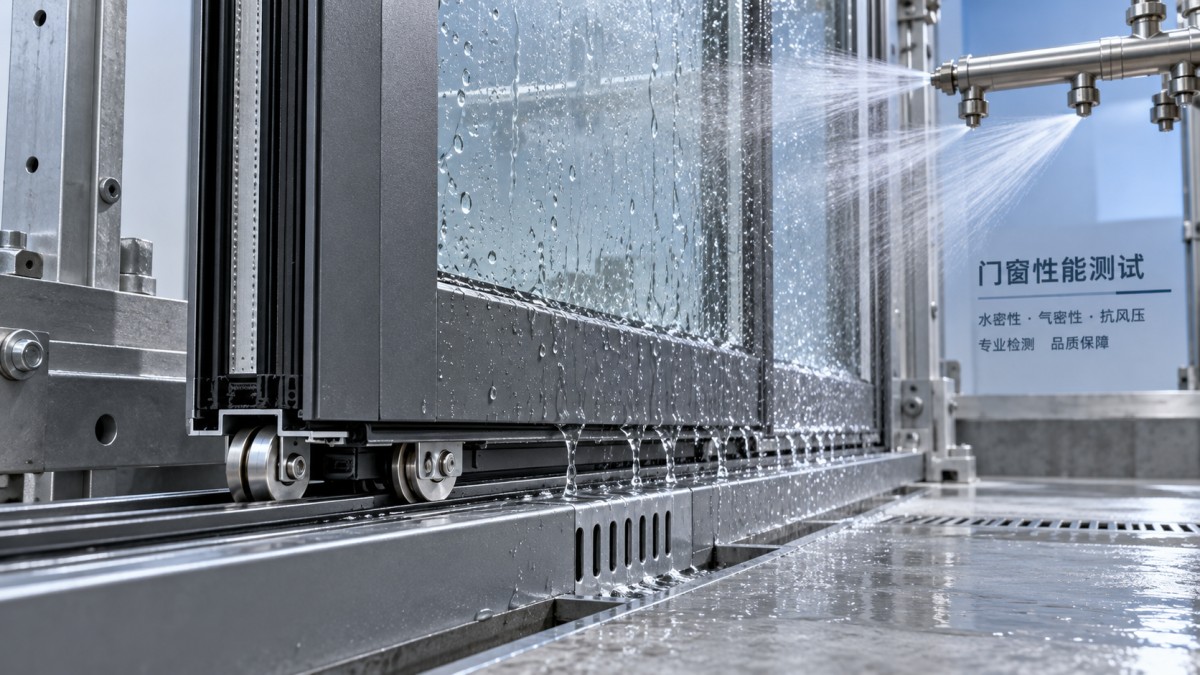
A performance figure becomes useful only when its test method, specimen configuration, and acceptance criteria are known. Start with applicability before comparing headline numbers.
Request the complete report or a verifiable certification record. A brochure stating “excellent waterproofing” cannot establish test pressure, leakage limits, or permitted product variations.
Match the tested specimen to the proposed opening: overall dimensions, panel arrangement, sliding direction, track count, glazing specification, interlocks, hardware, seals, and threshold construction.
Pay particular attention to maximum panel dimensions. A taller or wider sash may experience different deflection, seal contact, and roller loading than the tested specimen.
Check whether documented rules permit size extensions or component substitutions. Similar appearance, shared profile names, or matching alloy descriptions do not establish equivalent assembly performance.
Finally, confirm the report identifies the laboratory, specimen, standard edition, and results. Accreditation scope and independent certification can strengthen confidence, but neither replaces configuration matching.
What Does Maximum Sash Weight Actually Allow?
Maximum sash weight usually describes an allowable moving panel mass under specified conditions. It does not independently establish structural strength, opening force, or weather resistance.
Calculate the complete moving assembly, including glass, aluminum profiles, reinforcement, handles, locks, gaskets, and accessories. Glass weight alone can underestimate the demand on supporting hardware.
For preliminary estimates, ordinary glass weighs approximately 2.5 kilograms per square meter per millimeter of thickness. Confirm final weights using the actual glazing supplier’s data.
A two square meter unit containing two six millimeter glass panes therefore has approximately 60 kilograms of glass, before adding the sash frame and hardware.
Laminated glass, thicker panes, and additional components change this estimate. Use the final bill of materials when evaluating capacity, especially near the manufacturer’s published limit.
Ask whether the stated capacity applies to each roller, a roller pair, or the entire sash assembly. These descriptions cannot be treated as interchangeable.
Do not simply multiply individual roller ratings. Uneven adjustment, track irregularities, sash distortion, and load distribution can prevent all rollers from sharing weight equally.
The allowable configuration must satisfy every relevant restriction: sash mass, width, height, aspect ratio, glazing thickness, roller arrangement, and hardware compatibility. Meeting one limit is insufficient.
A proposed 180 kilogram sash against a documented 200 kilogram limit may appear acceptable, but dimensions, operating force, installation tolerances, and durability evidence still require review.
Will the Rated Sash Remain Practical to Operate?
Weight capacity describes support capability; users experience starting force, sustained sliding force, noise, and locking effort. Require operating evidence for the proposed panel size and mass.
Roller diameter, bearing construction, track finish, and alignment influence movement. Seal compression also matters: tighter contact can improve weather performance while increasing friction during operation.
Ask how opening force was measured, including sash position, locking state, conditioning, and maintenance. A measurement on a small demonstration panel may misrepresent project conditions.
Where accessibility requirements apply, compare measured forces and handle operation with the applicable project rules. A high load rating cannot establish compliance with accessibility requirements.
Durability evidence should identify cycle count, loading, maintenance, and acceptance criteria. Review whether repeated movement affected alignment, rollers, locks, seals, or subsequent weather performance.
For heavily used entrances, service access matters as much as initial smoothness. Confirm roller replacement procedures, adjustment access, spare part availability, and any required sash removal.
How Should You Compare Air Leakage Results?
Air leakage measures airflow through a closed assembly under a specified pressure differential. Lower leakage generally indicates tighter construction when the measurement conditions are comparable.
Common references include ASTM E283 for laboratory air leakage measurement and EN 1026 for testing, with EN 12207 providing classification within its applicable scope.
Compare results within the required standard and edition. An EN air permeability class cannot be directly substituted for an ASTM leakage value without supporting analysis.
Record the pressure differential and reporting basis. Results may be normalized by specimen area or opening joint length, and those values describe different measurement relationships.
A result of 0.5 liters per second per square meter at 75 pascals cannot be directly ranked against a result reported at 300 pascals.
Likewise, converting units does not resolve different pressures, specimen geometries, or procedures. Require comparable testing or a justified engineering interpretation before claiming one system performs better.
Inspect the likely leakage paths: meeting stiles, perimeter seals, sash corners, lock interfaces, and track junctions. Seal continuity often matters more than a profile’s visual thickness.
Ask whether the specimen was tested in its normal closed and locked condition. Temporary sealing or special preparation must be disclosed and assessed for relevance.
Air leakage is also separate from thermal transmittance. Energy assessment requires applicable U-factor information and glazing data, alongside air leakage and the intended installation details.
What Does a Water Resistance Rating Prove?
A water resistance rating establishes performance under defined spray and pressure conditions. It does not guarantee that every installation will remain dry during every storm.
ASTM E331 uses a uniform static pressure difference, while ASTM E547 uses cyclic static pressure. Their procedures should not be treated as identical evidence.
Within European testing frameworks, EN 1027 addresses watertightness testing and EN 12208 classification. Check the applicable method and exposure arrangement before interpreting the reported class.
For every result, obtain the pressure differential, water application rate, exposure duration, pressure sequence, and acceptance criteria. A pressure figure without these details is incomplete.
“No leakage at 300 pascals” is only useful when the report defines leakage and identifies the tested assembly. Ask where water was observed during testing.
Water entering an intended drainage cavity does not necessarily constitute failure. The governing procedure determines which locations and conditions represent unacceptable penetration into the interior.
Do not convert water test pressure directly into a universal wind speed rating. Building exposure, pressure coefficients, test assumptions, and local requirements complicate that relationship.
Also separate water resistance from structural wind resistance. A system can resist water at one pressure yet require independent evidence for strength and allowable deflection.
Select the required water performance using project specifications, applicable codes, and the responsible designer’s exposure assessment. Coastal locations and exposed elevations may need different requirements.
Why Thresholds, Drainage, and Installation Change the Outcome
Sliding systems manage water through coordinated barriers and drainage routes. Track chambers, weep openings, end seals, and pressure relationships must function together within the tested configuration.
A flush or reduced height threshold may change water management substantially. Request evidence for that exact threshold instead of relying on a raised threshold’s report.
Check drainage outlet locations against paving, finishes, and external drainage provisions. An outlet that works in a laboratory can become obstructed after surrounding construction is completed.
Installation must maintain frame alignment and appropriate support beneath the track. Distortion can affect roller loading, interlock engagement, seal compression, and drainage gradients simultaneously.
Review perimeter interfaces separately from product performance. Sill pans, membranes, flashing, sealant joints, and end dams must suit the wall assembly and manufacturer’s installation instructions.
Field testing can help evaluate installed performance. ASTM E1105 addresses water penetration testing of installed assemblies, but the project must define the procedure and acceptance requirements.
Nearby components also require interface coordination. Aluminum Art’s Aluminum alloy guardrail, model GFR-53, may require detailing alongside openings within residential or commercial projects.
For this aluminum accessory, verify fixing positions, required strength, finish durability, and installation access independently. Its product description does not establish sliding system weather ratings.
A Practical Approval Checklist for Technical Assessors
Build a comparison sheet around the project configuration and required performance. This prevents a strong result in one category from concealing missing evidence elsewhere.
- Define the opening: Record panel dimensions, arrangement, glazing, complete sash mass, threshold, exposure, expected usage, accessibility needs, and maintenance access.
- Verify mechanical suitability: Confirm complete sash capacity, dimensional limits, hardware configuration, operating force, durability evidence, and replacement provisions.
- Normalize air comparisons: Align test methods, pressure differentials, units, reporting bases, and specimen configurations before ranking results.
- Verify water evidence: Check test procedure, pressure, spray conditions, duration, penetration criteria, drainage details, and threshold applicability.
- Review installation: Assess supporting construction, perimeter sealing, drainage clearance, tolerances, and any specified field testing.
- Close evidence gaps: Obtain documented technical justification, applicable additional testing, or a configuration change before final approval.
For example, one supplier might offer a higher sash weight limit while another supplies stronger water test evidence. Neither automatically becomes the better project choice.
The preferred system must satisfy all mandatory criteria for the proposed configuration. Additional capacity has limited value if threshold performance or operating force remains unverified.
Where evidence is incomplete, make the outstanding requirement explicit. Avoid allowing a general supplier assurance to become an undocumented assumption in the final specification.
Specify the Configuration You Can Defend
The most useful aluminum sliding system rating is one that can be traced to a relevant test, a defined configuration, and a clear acceptance requirement.
Assess sash weight together with dimensions and operation; compare air leakage under equivalent conditions; and evaluate water resistance alongside threshold, drainage, and installation details.
Approve a system when the evidence supports the actual opening and exposure. That approach produces clearer specifications, stronger supplier comparisons, and fewer avoidable performance disputes.