


Replacing Aluminum Door Handles: Spindle and Fixing Measurements
A replacement handle fits an aluminum door only when its spindle, fixing pattern, and mounting arrangement match the existing hardware. A similar-looking backplate is not enough: the wrong spindle can fail to engage the lock correctly, while misplaced fixings can leave the handle loose or interfere with the lock case.
The essential measurements are the spindle’s square size and working length, the fixing-hole center distances, and the door thickness at the mounting position. On handles with a cylinder opening, the spindle-to-cylinder distance must also match. These dimensions describe different interfaces and should be recorded separately before ordering a replacement.
Check whether the handle is actually the faulty part
Test the door while it is open before removing hardware. Operate the lever, release it, and observe whether the latch retracts fully and the lever returns. Where a multipoint lock is fitted, follow its operating sequence without forcing the mechanism. Some locks have an anti-misoperation device that prevents operation with the door open; use the manufacturer’s procedure rather than bypassing it.
If the handle operates normally with the door open but becomes stiff when the door closes, check the strike alignment, hinge position, and seal compression. Replacing the handle will not correct a latch or locking point being forced against its keep.
If movement is poor in both positions, the fault could involve the handle spring, spindle, lock follower, or mounting pressure. Support both handle assemblies during removal and keep the door securely open. Once the handle is detached, check the lock with the correct spindle or approved service tool. A follower that remains stiff or fails to retract the latch indicates a problem beyond the visible handle.
On a fire-rated, escape-route, or security-rated doorset, replacement hardware must remain compatible with the approved assembly. Matching dimensions alone does not establish that a substitute preserves the door’s required performance.
Separate fixing centers from lock centers
Two measurements are easily confused because both appear on a long handle backplate. Fixing centers describe the distance between mounting screw axes. Lock centers, often called the PZ dimension on cylinder-operated hardware, describe the distance between the spindle axis and the cylinder’s rotational axis.
Neither measurement can substitute for the other. A handle can match the cylinder position perfectly while its screws miss the existing holes. Conversely, matching screw holes do not guarantee that the spindle and cylinder openings align.
Record the spindle-to-fixing offsets as well as the overall fixing-center distance. Two backplates can have identical screw spacing but place the spindle differently between those screws. For a Euro-profile cylinder, use the center of the circular upper portion of the cylinder profile—not the center of the complete keyhole-shaped opening—as the cylinder-axis reference.
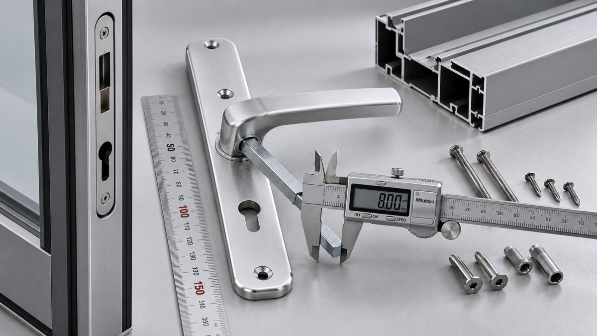
Measure the spindle without assuming a standard size
Remove the spindle and measure across its flat faces with a caliper. Measuring diagonally across the corners gives the wrong size. Clean away dirt or loose corrosion, and measure an unworn section where possible. An 8 mm square spindle is a common size in lever-handle systems, but it should not be assumed merely because the door or handle is aluminum.
Check the spindle construction as well as its dimensions. A solid square bar, split spindle, stepped spindle, and offset arrangement are not automatically interchangeable. Split-spindle systems can allow different operation from inside and outside. Replacing one with a continuous bar can change access behavior even if the levers appear to work.
Inspect for rounded corners, twisting, cracks, and wear near retaining screws. Excessive play can come from a worn spindle, but it can also come from damage inside the handle hub or lock follower. A new spindle will not restore a follower whose square opening has become enlarged.
Measure the existing spindle’s overall length, then establish why that length works. Its usable length must accommodate the distance between the handle assemblies and provide the specified engagement in both hubs. Door thickness alone is insufficient because different backplates, roses, and handle hubs place their engagement points at different depths.
A spindle that is too short may engage one handle only shallowly and slip under load. A spindle that is too long may bottom out inside a closed hub, prevent the plates from seating, or create binding when the fixing screws are tightened. Do not pull a poorly seated assembly into position with the screws.
Use the replacement manufacturer’s permitted door-thickness range and engagement requirements wherever available. If the spindle is designed to be cut, shorten it according to those instructions, deburr the end, and preserve any required groove or retaining feature. Special-purpose or split spindles should not be modified as though they were plain square bar.
Capture the complete fixing pattern
Remove decorative covers where necessary to identify the actual mounting arrangement. A handle may use through-bolts, threaded posts, screws into reinforced profile sections, or concealed fixings beneath a rose. The visible screw head does not necessarily reveal how the assembly is secured.
Measure from hole center to hole center, not between screw-head edges. For two equal-diameter circular holes, measuring from the same edge of one hole to the corresponding edge of the other gives the center distance. If the holes are unequal, elongated, or damaged, establish each center independently rather than applying this shortcut.
Include every fixing position on a sketch. Record horizontal offsets, hole diameters, and whether the holes are threaded or clearance holes. Where the replacement uses posts or mounting sleeves, check their outside diameter and insertion depth: a screw may fit while its supporting post does not.
Through-bolts must follow a path compatible with the lock case. Matching the external backplate pattern does not prove that a new bolt can pass through the door without striking the lock mechanism. Check the lock manufacturer’s fixing provisions before drilling or changing bolt positions.
Aluminum profiles introduce an additional constraint: the visible wall may be thin, with reinforcement located only at designated fixing points. Moving a screw into an unsupported area can produce a handle that initially feels secure but loosens under repeated use. Enlarging holes can also damage nearby profile features, including thermal breaks.
A replacement should ideally use the existing engineered mounting locations. An oversized backplate may cover old holes cosmetically, but it does not repair a damaged fixing substrate or create a sound new attachment point.
Measure thickness where the handle actually mounts
With the door open, measure between the interior and exterior surfaces on which the handle plates will sit. Avoid using the overall depth of a stepped profile if the plates mount on recessed faces. Likewise, glazing beads, weather seals, and decorative trims should not be included unless they genuinely form part of the mounting stack.
Record any packers or adapters separately. Their thickness affects the spindle span and screw length, but their role also matters: a shaped adapter may provide a flat seat on an uneven profile. Omitting it can make the backplate rock even when the fasteners are tight.
For through-fixed handles, door thickness is only part of the screw-length calculation. Backplate construction, receiving posts, washers, and required thread engagement also contribute. Use the specified fastener type and size; an existing screw should not be reused merely because it reaches the new assembly.
A screw that is too long can bottom out in a blind post before clamping the plates. One that is too short may catch only a few threads. Both conditions can be mistaken for a defective handle. Confirm that the screw achieves proper engagement and clamping without protruding into moving components.
Confirm compatibility beyond the measurements
Before accepting a replacement, compare the handle arrangement. Lever/lever and lever/pad sets may provide different outside operation. Handed handles, offset spindles, and fixed external pads require more than a dimensional match. Specify the door’s opening direction and the required inside/outside function using the supplier’s handing convention.
Also check whether the original handle is sprung or unsprung. A sprung handle provides its own return assistance; an unsprung version relies more heavily on the lock’s return mechanism. The replacement must suit the lock rather than merely produce an acceptable lever position during an unloaded trial.
On narrow aluminum stiles, backplate width and lever clearance can rule out an otherwise compatible set. Check clearance to the frame, cylinder, glazing bead, and adjacent hardware throughout the lever’s travel. Verify that the cylinder remains properly accessible and that any protective escutcheon still fits as intended.
A useful replacement request includes a dimensioned sketch, photographs of both sides and the door edge, the lock’s identification markings, spindle details, mounting method, thickness, and required operating function. Keep finish and appearance separate from these compatibility requirements so that a visually similar substitute is not mistaken for a direct replacement.
Use installation behavior to identify remaining errors
Trial-fit the spindle and both handle assemblies before final tightening. The plates should sit flat without being pulled into place by the screws. Tighten fixings evenly to the manufacturer’s specified torque, avoiding impact tools unless expressly permitted. Excessive clamping can distort a plate or compress a hollow profile.
If the lever becomes stiff only as the screws are tightened, check alignment, spindle length, adapters, and contact between fasteners and the lock case. Simply leaving the screws loose conceals the cause and creates another service problem.
Test operation with the door open, then closed. Confirm full latch retraction, free lever return, cylinder operation, and any multipoint locking sequence. Test inside and outside independently, especially where a pad or split spindle controls external access. Keep alternative access available during these checks to avoid an accidental lockout.
If play remains after correct fitting, identify its source. Movement between the backplate and door suggests a mounting problem; movement within a stationary handle assembly suggests wear or clearance in the hub, spindle, or follower. Treating both symptoms by tightening harder risks damage without correcting the fault.
The completed repair should leave the handle firmly mounted, the latch and locking points operating without force, and the original access function intact. Record the verified dimensions and replacement reference against the door location. That record is more useful for the next repair than a photograph of the finish alone.
Related Posts
CONTACT US

First class quality service and professional after-sales team.
Get in Touch
*We respect your confidentiality and all information are protected.